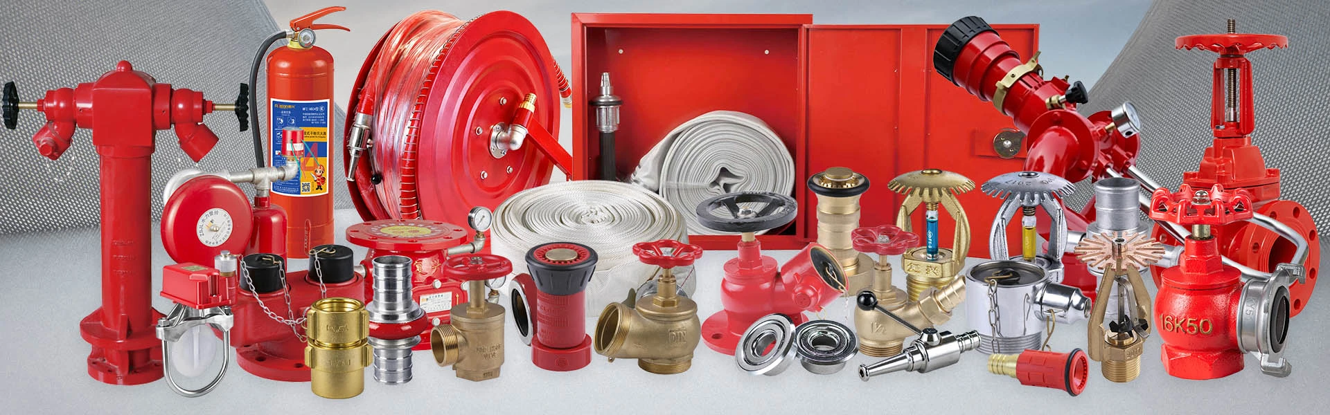
Flanged Ratio Pressure Reducing Valve for Water Pipelines
The flanged ratio pressure reducing valve for water pipelines is designed to reduce water pressure by using the difference between the effective pressure areas at both ends of the internal piston. As a type of pressure reducing valve, it creates a fixed proportional relationship between inlet and outlet pressure rather than holding the outlet at a constant value. The flanged connection makes it a direct fit for rigid water pipeline systems in metallurgy, petroleum, hydraulic systems, water pressure testing units, residential water supply and high-rise building water supply.
Available pressure reduction ratios include 2:1, 3:1, 4:1, 3:2 and 5:2. The valve reduces both dynamic and static pressure and is suitable for water-based pipeline systems requiring proportional pressure control. Because the connection is flanged, the valve can be dropped into a pipeline run between standard flanges and isolated for maintenance without disturbing the rest of the network.
How the Flanged Valve Fits a Water Pipeline
A water pipeline is a chain of components, and the pressure reducing valve is one link in that chain. A well-planned installation places the valve in a sequence that protects it and keeps the line serviceable:
- Upstream isolation — a gate valve or butterfly valve before the reducing valve, so the valve can be serviced without draining the main.
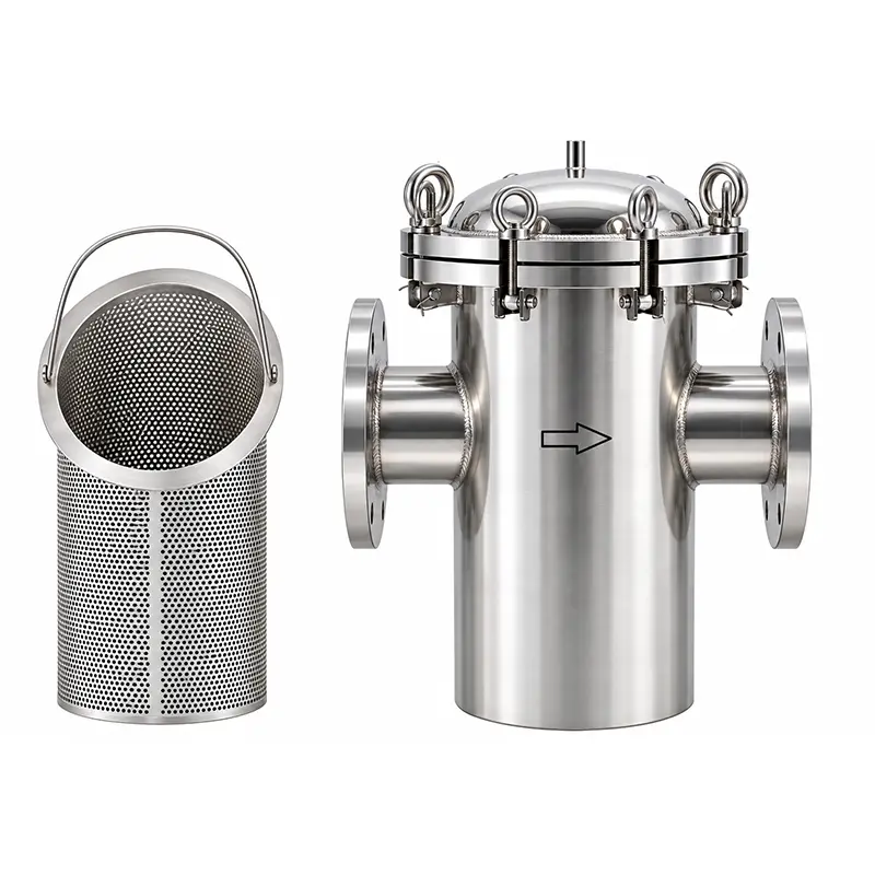
- Upstream filtration — a Y-type strainer to stop debris from entering the valve body and scoring the piston or seat.
- The reducing valve itself — flanged into the run, with the small hole on the valve body kept from facing upward.
- Downstream isolation — a second gate or butterfly valve for maintenance and pressure testing.
- Downstream protection — where overpressure is a risk, a pressure relief valve or holding pressure relief valve.
This sequence is not optional for a reliable installation. Debris is the most common cause of a reducing valve failing to hold its ratio, and isolation valves are what make future maintenance practical.
Working Principle
The valve operates according to the force balance between different effective piston areas. The relationship can be expressed as P1 × S1 = P2 × S2, where P1 and P2 represent inlet and outlet pressure, while S1 and S2 represent the effective pressure areas at both ends of the piston.
Because the two effective areas are different, the inlet and outlet pressures maintain a predetermined proportional relationship. The outlet pressure changes with the inlet pressure rather than remaining completely constant. The pressure reduction ratio is set by the matched internal valve core and cylinder liner — different component dimensions create different effective pressure areas — and cannot be continuously adjusted during operation. A different ratio requires a corresponding valve core and cylinder liner configuration.
Technical Data
|
Parameter |
Specification |
|
Standard |
GB/T 21386-2008 |
|
Nominal Diameter |
Available DN sizes should be confirmed according to the selected model |
|
Rated Working Pressure |
1.6 MPa |
|
Minimum Opening Pressure |
0.2 MPa for 2:1 / 0.3 MPa for 3:1 |
|
Pressure Ratio |
2:1, 3:1, 4:1, 3:2, 5:2 |
|
Valve Body |
Ductile Iron, Stainless Steel |
|
Medium |
Water |
|
Temperature |
≤80°C |
|
Connection |
Flanged |
The nominal diameter should be selected according to pipeline size, flow rate, inlet pressure, pressure reduction ratio and overall operating conditions.
Installation Requirements for Water Pipelines
The pipeline should be cleaned before installation, and a Y-type filter should be installed upstream to prevent debris from entering the valve. Gate valves or butterfly valves can be installed before and after the valve for easier maintenance.
For systems requiring continuous water supply, two valves of the same nominal diameter can be installed in parallel. The small hole on the valve body must not face upward, as water or debris entering the hole may affect valve operation. Where the pipeline feeds a fire protection branch, the reducing valve is often installed upstream of the fire pump suction or discharge line, depending on the system design.
Applications in Water Pipeline Systems
The flanged ratio pressure reducing valve for water pipelines is suitable for metallurgy, petroleum-related systems, hydraulic systems, water pressure testing units, residential water supply systems and high-rise buildings. It can be used in pressure zoning applications where downstream pressure needs to maintain a proportional relationship with upstream pressure — for example, dividing a tall building into pressure zones fed from a common riser.
Related pipeline equipment from FUXEON® includes check valves, ball valves, water flow indicators and fire hydrants, all of which can be specified alongside the reducing valve for a complete pressure-controlled system.
Quality Control
FUXEON® has multiple machining and production facilities and can manufacture several thousand pressure reducing valves per month. Each finished valve undergoes a 2.4 MPa pressure test with a 5-minute holding period to check valve strength and sealing performance before delivery. FUXEON® holds GB/T 19001-2016 / ISO 9001:2015, GB/T 24001-2016 / ISO 14001:2015, GB/T 45001-2020 / ISO 45001:2018 and GB/T 27922-2011 certifications. Full documents are available on our certificate page.
Frequently Asked Questions
Q: What flange standard does the valve use?
A: The valve is supplied with flanged ends to suit the selected model and project requirement. Confirm the flange standard, pressure rating and DN at the order stage so that the valve matches the pipeline flanges without adapters.
Q: Do I need a strainer upstream of the reducing valve?
A: Yes. A Y-type strainer upstream is strongly recommended. Debris entering the valve can score the piston or seat and disturb the pressure ratio.
Q: Can the valve be installed vertically?
A: The valve can be installed in a vertical run provided the small hole on the valve body does not face upward. Water or debris entering that hole can affect operation, so orientation should be checked on site before bolting up.
Q: Should I install isolation valves before and after the reducing valve?
A: Yes. A gate valve or butterfly valve on each side allows the valve to be serviced or replaced without draining the pipeline.
Q: How should the pipeline be prepared before installation?
A: Flush and clean the pipeline first. Welding slag, scale and construction debris are the most common causes of a reducing valve failing to hold its ratio after commissioning.
Q: Can two valves be installed in parallel?
A: Yes. For systems requiring continuous water supply, two valves of the same nominal diameter can be installed in parallel, so one can be isolated for maintenance while the other stays in service.
Need a flanged ratio pressure reducing valve matched to your pipeline flanges?
Factory-direct supply · Pressure-tested before delivery · Export to 50+ countries
Related Products

Hot Products
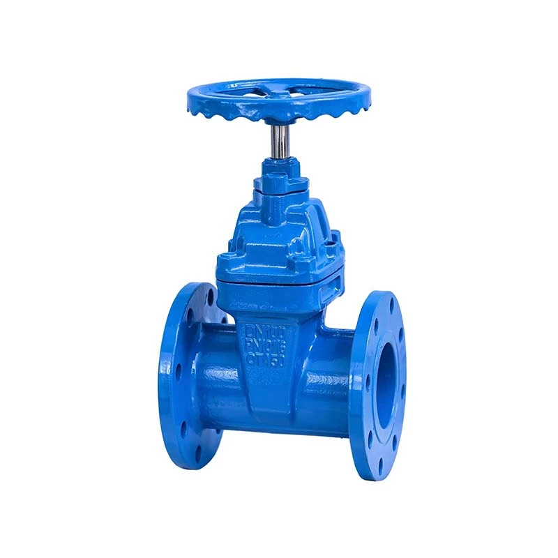
NRS Gate Valve
FUXEON®'s NRS gate valve features a dust ring and triple O‑ring design for excellent sealing, and the gate is encased in rubber for superior corrosion resistance. Our valves are coated with a harmless epoxy resin electrostatic powder, making them suitable for both building and food‑grade piping. As a professional manufacturer and reliable supplier from China, our factory ensures stable quality and consistent performance for every valve. For custom gate valve requests, please contact us.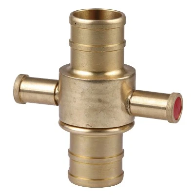
BSP Fire Coupling
FUXEON® is a professional manufacturer of BSP fire couplings with years of rich production experience. Based in China, our factory boasts a complete production line from casting and machining to final product assembly, ensuring high cost-effectiveness of products. As a reliable supplier, we mainly provide standard 1.5”, 2”, and 2.5” BSP fire couplings that meet the requirements of the UK Fire Service and various fire-related facilities, and also offer customized production services according to customer needs.
Vertical Foam Bladder Tank
FUXEON®'s vertical foam bladder tank consists of a pressure tank, bladder, proportioner, safety valve, vent valve, pressure gauge, check valve, and various control valves and piping. Pressurized water is supplied by a pump unit, displacing the foam in a specific ratio and mixing it with the pressurized water to form a foam mixture. It is an ideal choice for oil depots, refineries, chemical plants, and other similar locations.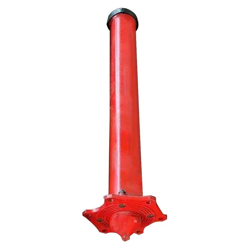
GOST Underground Steel Fire Hydrants
FUXEON® GOST underground steel fire hydrants are high-performance, cost-effective fire-fighting water supply equipment designed strictly according to GOST standards. The products feature a robust steel structure, alkyd resin anti-corrosion coating, and flange-threaded double-end connections, ensuring stable operation and a service life of up to 30 years. They are manually operated via a center key with an opening torque of 105 N·m and are suitable for temperatures ranging from 5℃ to 90℃. Proven reliable in actual industrial projects, the products are easy to maintain and highly compliant. FUXEON® is a trustworthy Chinese manufacturer and professional supplier that meets the global GOST standard fire infrastructure requirements.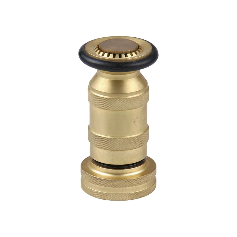
NPT Fire Nozzle
FUXEON® NPT Fire Nozzle is one of the important fire-fighting equipment, and it is manufactured in China. It is used to connect fire hoses and can spray water streams of different shapes, with the advantages of a wide spray range and high flow rate, commonly used for fire extinguishing or irrigation.
NPT Fire Coupling
The FUXEON® NPT fire coupling is a high-performance firefighting connection component precision-manufactured from brass or aluminum. It features robust durability, reliable sealing performance, and quick connection capability, serving as a critical bridge for linking fire hoses to fire hydrants, water guns, and fire engines. As a professional China-based manufacturer, we integrate strict quality control throughout the production process, from casting to machining, ensuring the product meets stringent fire application standards.
- Related Blog
- Reviews