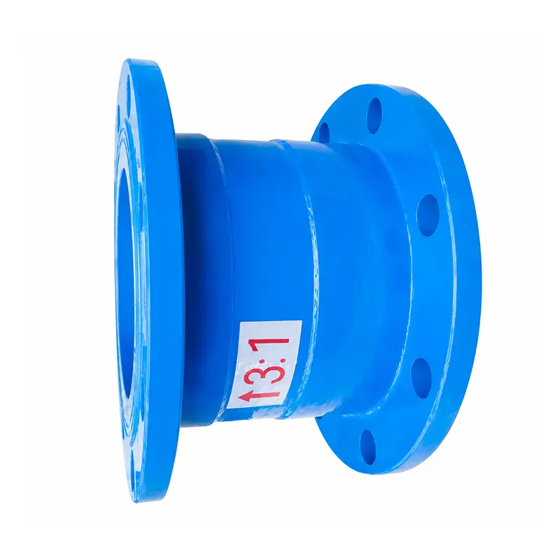
Ratio Pressure Reducing Valve for Large Diameter Water Pipelines
The ratio pressure reducing valve for large diameter water pipelines is designed for mains and risers where the pipe size is driven by flow rather than by pressure. It reduces water pressure using the difference between the effective pressure areas at both ends of the internal piston, producing a fixed proportional relationship between inlet and outlet pressure. In large diameter service, correct sizing matters more than in small lines: an undersized valve adds unnecessary pressure loss, while an oversized valve can operate away from its intended flow range.
Available pressure reduction ratios include 2:1, 3:1, 4:1, 3:2 and 5:2. The valve reduces both dynamic and static pressure, which is important in large water pipelines where long static periods are followed by sudden high-flow demand.
Why Diameter Selection Is Different for Large Pipelines
In a large diameter line the valve is a significant resistance element. As flow increases, pressure loss across the valve and pipeline may also change, and the actual outlet pressure will reflect both the ratio and the losses in the surrounding system. For accurate engineering selection, the nominal diameter, operating flow rate, inlet pressure range and required outlet pressure should be considered together.
Three sizing traps are common in large diameter projects:
- Sizing by pipe diameter alone. A DN that matches the adjacent pipe may be far larger than the valve needs, pushing operation toward the low end of its flow range.
- Ignoring inlet pressure variation. Because the outlet tracks the inlet proportionally, a large swing in supply pressure produces a proportionally large swing downstream. The downstream system must be designed for that swing.
- Forgetting pipeline resistance. Losses in strainers, fittings and long runs add to the valve's own loss and reduce the pressure available at the point of use.
Flow-pressure performance data should therefore be based on the selected valve size and actual test conditions rather than on a generic curve.
Technical Data
|
Parameter |
Specification |
|
Standard |
GB/T 21386-2008 |
|
Nominal Diameter |
Available DN sizes should be confirmed according to the selected model |
|
Rated Working Pressure |
1.6 MPa |
|
Minimum Opening Pressure |
0.2 MPa for 2:1 / 0.3 MPa for 3:1 |
|
Pressure Ratio |
2:1, 3:1, 4:1, 3:2, 5:2 |
|
Valve Body |
Ductile Iron, Stainless Steel |
|
Medium |
Water |
|
Temperature |
≤80°C |
|
Connection |
Flanged |
The nominal diameter should be selected according to pipeline size, flow rate, inlet pressure, pressure reduction ratio and overall operating conditions.
Choosing the Ratio for Large Water Supply Systems
The ratio is a structural design parameter set by the internal valve core and cylinder liner. It is not adjustable in service, so it must be chosen correctly at the order stage. Industry practice provides useful upper limits:
|
System Type |
Typical Ratio Limit |
Reason |
|
Domestic water supply |
Generally no more than 3:1 |
Keeps downstream pressure within fixture tolerance as the inlet varies |
|
Fire protection systems |
Generally no more than 4:1 |
Preserves adequate pressure at the most remote outlet |
|
Domestic hot water |
Generally no more than 2.5:1 |
Protects hot water equipment and limits temperature/pressure interaction |
In high-rise buildings, large diameter risers are often divided into pressure zones, with a reducing valve at each zone boundary. The ratio is then chosen so that the zone below receives a proportionate share of the riser pressure, and the equipment in that zone — fire hydrants, fire sprinklers, alarm valves — is rated for the pressure it will actually see.
Parallel Installation for Continuous Supply
Large water pipelines often cannot be shut down for maintenance. For systems requiring continuous water supply, two valves of the same nominal diameter can be installed in parallel, with isolation valves on each branch. One valve stays in service while the other is isolated, inspected or replaced.
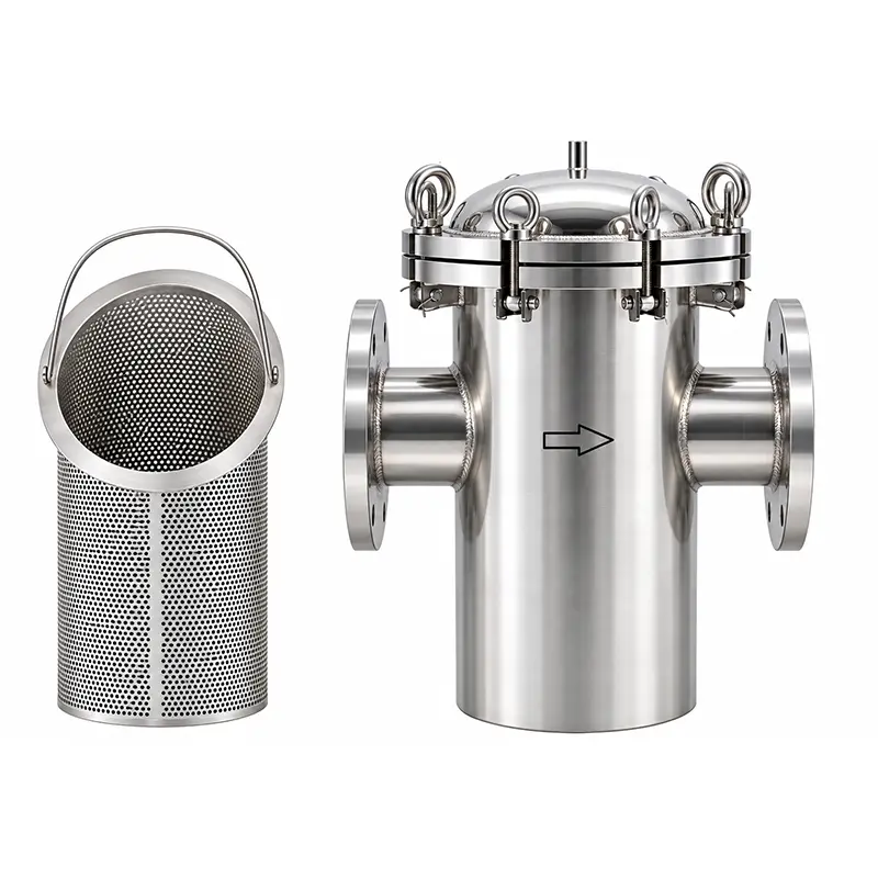
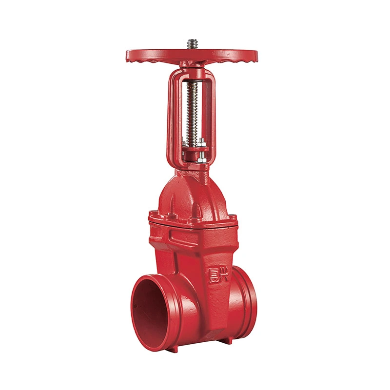
The same installation rules apply on each branch: clean the pipeline before installation, fit a Y-type filter upstream to stop debris entering the valve, provide a gate valve or butterfly valve before and after for maintenance access, and keep the small hole on the valve body from facing upward.
Frequently Asked Questions
Q: How do I choose the DN for a large diameter line?
A: Select the DN from the pipeline size, operating flow rate, inlet pressure, required ratio and overall operating conditions together — not from the adjacent pipe diameter alone. Confirm the available DN range against the specific model.
Q: How does flow affect the outlet pressure?
A: The hydraulic performance is affected by nominal diameter, inlet pressure, ratio, flow rate and pipeline resistance. As flow increases, pressure loss across the valve and pipeline may change, so the actual outlet pressure will differ from the static ratio calculation.
Q: Can two large valves be installed in parallel?
A: Yes. For systems requiring continuous water supply, two valves of the same nominal diameter can be installed in parallel so that one remains in service while the other is maintained.
Q: What ratio should a high-rise building use?
A: The ratio is selected by zone. As general industry limits, domestic water supply is generally no more than 3:1, fire protection systems generally no more than 4:1, and domestic hot water generally no more than 2.5:1.
Q: Does a large diameter affect the accuracy of the ratio?
A: The ratio itself is set by the internal piston areas and remains structural. However, at very low flow the valve may operate near its opening threshold, and at very high flow pipeline resistance becomes significant. Both should be checked during selection.
Q: How do I obtain flow-pressure data for a specific size?
A: Request the data for the selected valve size and your actual operating conditions. Performance should be based on the chosen size and test conditions rather than a generic curve — our team can supply this through the inquiry page.
Working on a large diameter water pipeline project?
Multiple DN options · Ratios 2:1 to 5:2 · Flanged connection
Related Products
Hot Products
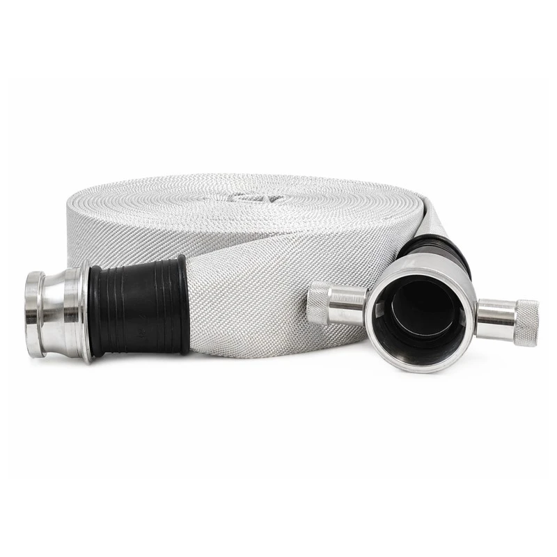
2.5-Inch Fire Hose
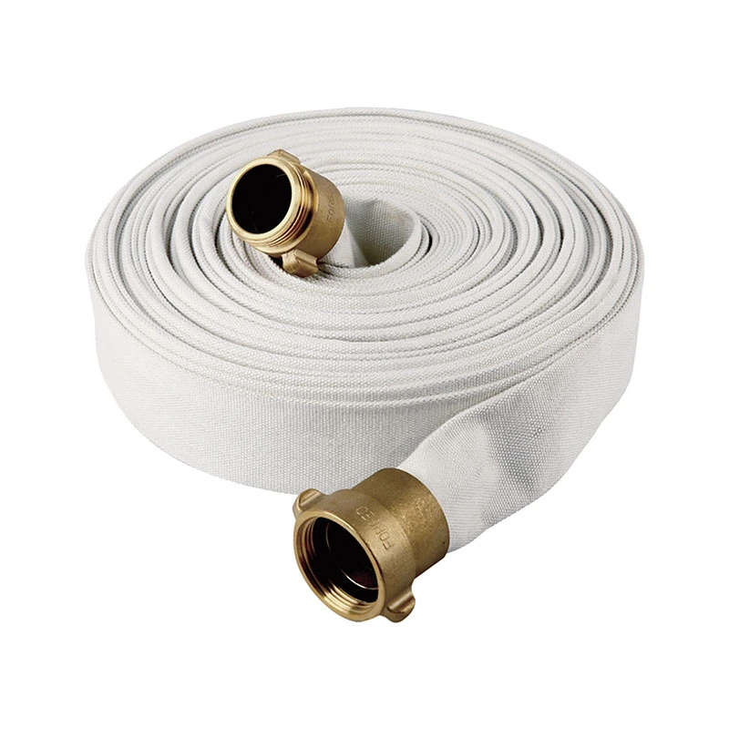
FUXEON® 2.5-inch fire hose is a versatile water delivery product independently developed and manufactured by a professional Chinese fire hose factory. Adhering strictly to international standards BS336 and BS6391, it features a high-strength woven polyester outer layer and various liner options. It offers advantages such as lightweight construction, kink and twist resistance, high-pressure durability, and long service life. As a professional and reliable supplier, FUXEON® offers comprehensive customization options—including size, color, length, and branding—making the hose suitable for diverse applications such as firefighting and rescue, construction, agricultural irrigation, and industrial drainage. It has earned long-term recognition from global customers for its consistent quality.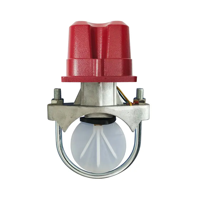
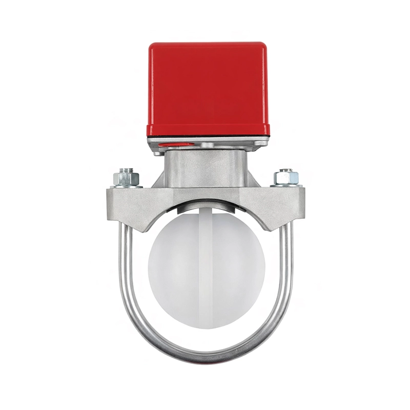
Waterflow Detector
The waterflow detector produced by FUXEON is designed and manufactured in accordance with GB5135.7-2018. It is an alarm device in an automatic sprinkler fire extinguishing system that converts waterflow signals into electrical signals and is equipped with a delayed false alarm prevention function.
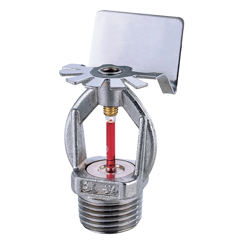
Glass Ball Fire Sprinkler
Fuxeon® is a Chinese manufacturer of glass ball fire sprinklers. We use brass as raw material and the glass bulbs are from the world-renowned JOB brand. Our fire sprinklers are high-quality, competitively priced, and fully certified. We also offer OEM services. If you require a custom fire sprinkler, please contact us.
Upright Sprinkler
FUXEON® upright sprinkler heads are high-performance automatic fire extinguishing devices independently developed and manufactured in a professional Chinese factory, specifically designed for open-plan fire protection scenarios without suspended ceilings. The product is installed vertically on the sprinkler water supply branch pipe, spraying 80%-100% of the water volume downwards in a parabolic pattern. It utilizes a high-precision temperature-sensing glass bulb from JOB Germany and is constructed entirely of brass, offering advantages such as rapid response, stable performance, corrosion resistance, and long service life. As a professional manufacturer and supplier, FUXEON® provides standardized products, customized OEM/ODM services, and full-cycle technical support for global industrial and commercial fire protection projects.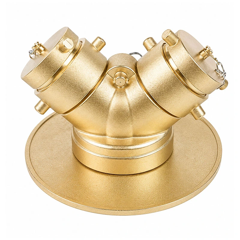
Siamese Connection
The siamese connection produced by FUXEON® is a key component specifically designed for professional fire protection systems. This dual-connector is made of high-quality brass, offering excellent durability and corrosion resistance. It serves as a standardized water inlet point, enabling fire trucks to efficiently replenish water supply to building sprinkler or riser systems in emergencies.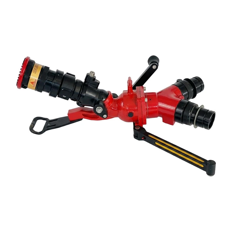
Fire Ground Monitor
FUXEON® fire ground monitor is feature-rich and have a long range. Made of aluminum alloy, they are lightweight and easy to carry, and feature a foldable support stand, allowing for flexible application in areas inaccessible to fire trucks and extending the protection range.
- Related Blog
- Reviews